


The AZDelivery D1 Mini NodeMcu WiFi Board ESP8266-12F CH340G WLAN ESP8266 Micro USB Lua Module 3.3V 500mA compatible with Arduino is a cheap, yet well-built, board available on Amazon that you can program and make perform some tasks. Its price is £4.99 on Amazon UK at the time of writing (it should be the same model offered by Envistia Mall on Amazon US for $6.39) and it promises some fun during your first steps in IoT programming.
Equipped with a powerful ESP8266 processor and integrated WLAN, the D1 Mini Wifi development board comes with the CH340 chip, which makes programming of the board simple and easy with Arduino-IDE. Its compact design and light weight allow its use for various applications and projects. For example, with the right sensors, it can be used to measure air pressure, temperature, and humidity through its own web server via a WLAN connection.
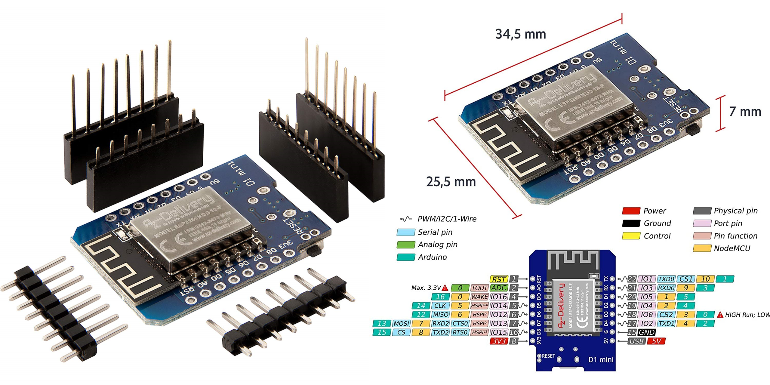
Specifications
- WLAN standard 802.11b/g/n
- 9 digital input/output pins, all pins have interrupt / PWM / I2C / 1 wire
- Main chip: ESP8266 CH340G
- 1 analog input (3.3V max. input)
- Dimensions: L = 34mm, W = 26mm, H = 8mm
- Energy consumption: Up to 500mA
- I / O Pins: 9, Weight: 3g
Let’s start!
Step 1: Download Arduino IDE. You can find it on the Arduino website https://www.arduino.cc/en/software
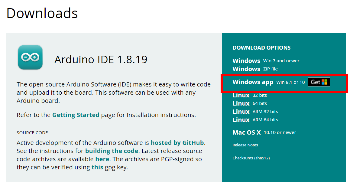
We downloaded the Windows app.
Step 2: Connect the board to your computer via USB. You should see a flashing blue LED on the board that will tell you that the drivers are correctly loaded.
Step 3: Launch Arduino IDE and change preferences. Arduino software needs all information about ESP8266-12F. You can add this information by entering the following address under Preferences → Additional Boards Manager URLs:
http://arduino.esp8266.com/stable/package_esp8266com_index.json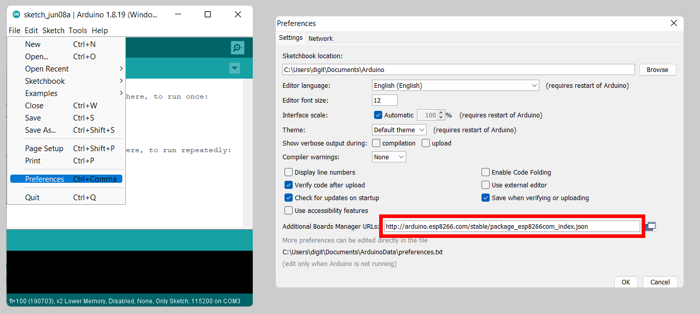
Confirm the operation by clicking “OK”.
Step 3: Install the ESP8266 library. When this is done, go to Tools → Board → Boards Manager and install the ESP8266 library. In the Boards Manager, enter “ESP8266” in the search bar at the top right. The package esp8266 by ESP8266 Community will be displayed. Choose the latest version (3.0.2) and click on “Install”.

The green text “INSTALLED” will appear after successful installation.
Step 4: Select the right board. To do this, go to:
Tools → Board: “Generic ESP8266 Module”
Tools → Flash Size: “4M (FS:1MB OTA…)”
Tools → Port: “COMxx” (here goes your serial adapter port)

Step 5: Write your first code. Make the LED on the ESP8266 blink. To do this, go to File → Examples → 01.Basics → Blink.

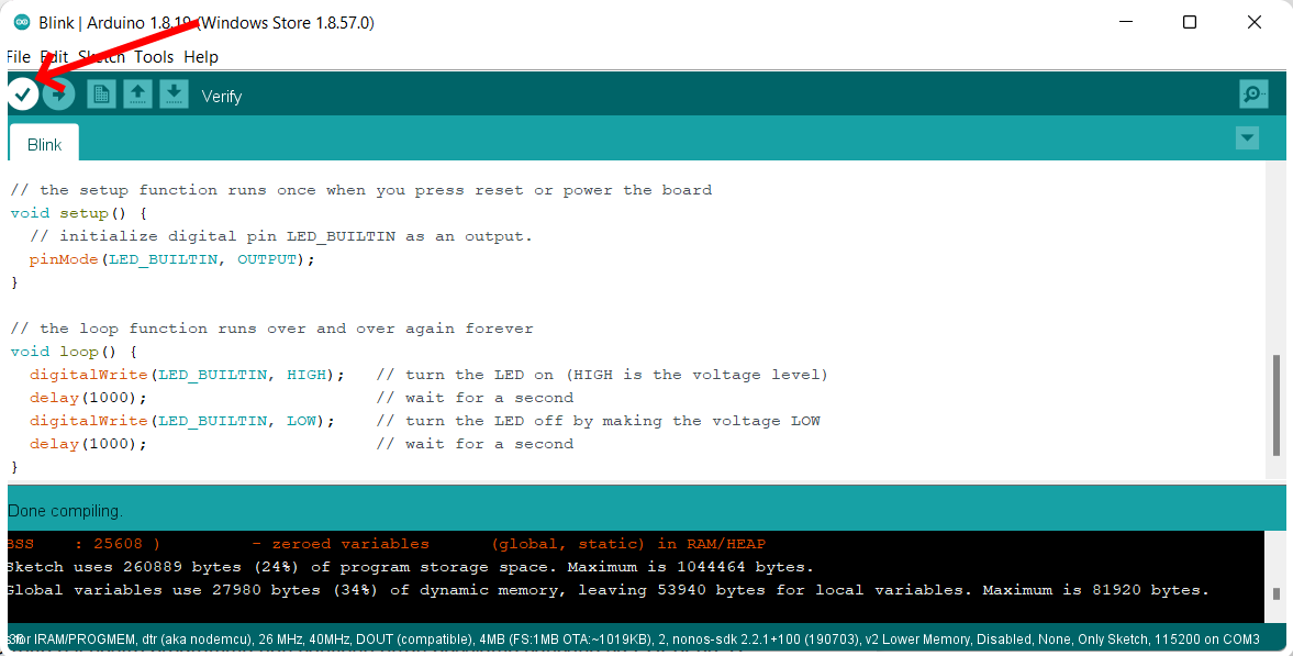
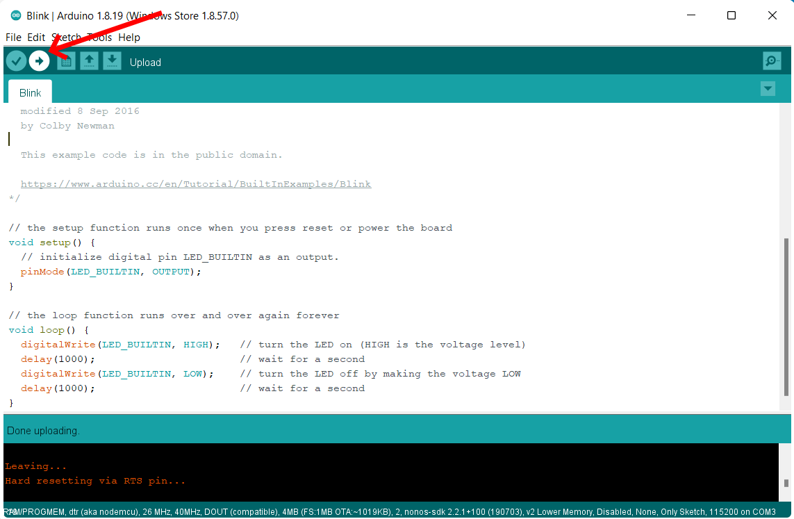
Step 6: Verify the code. The code should look like this:
// the setup function runs once when you press reset or power the board
void setup() {
  // initialize digital pin LED_BUILTIN as an output.
  pinMode(LED_BUILTIN, OUTPUT);
}

// the loop function runs over and over again forever
void loop() {
  digitalWrite(LED_BUILTIN, HIGH);   // turn the LED on (HIGH is the voltage level)
  delay(1000);                       // wait for a second
  digitalWrite(LED_BUILTIN, LOW);    // turn the LED off by making the voltage LOW
  delay(1000);                       // wait for a second
}
Now verify the code by clicking the corresponding button:
Step 7: Upload the code. If verification is successful, everything is correct and your program does not contain errors, you can now upload it to the ESP8266 by clicking the corresponding button:
That’s it. You should now see the small blue LED on the board blinking every second 😉
You can now play with all the other many examples available on Arduino IDE and start familiarizing yourself with the various possible instructions. Remember that this board has a wi-fi integrated, and can work as a web server, thus you can make it perform various actions through the Internet.


No Comment